First, a background:
Last year the team purchased two HD GoPro Hero 3 cameras and an underwater housing that holds the cameras side by side. In this configuration, the cameras can collect depth information which can be fed into the sonar model to reconstruct some of the finer details present in cisterns. While we already have some pretty good sonar generated models, our sonar head has a limited resolution. We would like to be as accurate as possible when reconstructing the intricate surfaces inside the cisterns we deploy into, so last year we attempted to fuse some stereo data into the cistern mesh using "disparity maps" and "projective texturing".
We had limited success with last year's solution due to the fact that some of the best disparity mapping algorithms around were not robust enough to handle compressed fish-eyed occluded underwater pictures with sediment floating around. In addition, it was difficult to collect a full set of pictures of the walls of cisterns. We learned A LOT last year, and have appropriately readjusted our goals for this project. They are as follows:
1) Reincorporate GEOMETRY data captured via stereo into the model as accurately as possible
2) Reincorporate COLOR data captured via stereo into the model in a visibly appealing way
This year, I will be working on #1, and Spencer will be working on #2.
In our advanced computer graphics class we have been discussing various geometric modeling techniques, and I have come up with a few ideas. We now have a pretty good way to produce disparity maps (MATLAB has a great built in function to cover this for us). We still plan to fuse the data in our disparity maps into the sonar model, but now we have thought of a better way to do it.
Disparity maps can be thought of as a 'point cloud', or, a way of representing a ton of discrete points in 3D space. To picture this, the x and y coordinates of each point in the disparity map are stored in pixel space in the image, and the z coordinate of each point is stored in the intensity of the color value in the picture. Here's a picture of an aloe plant, and its corresponding disparity map:

 We have a ton of disparity maps from inside the cisterns last year, but in my program I have been playing around with the aloe plant because I like it. What I have done is set up virtual projectors in a model scene, which PROJECT a point cloud based on a disparity map that is loaded in. This program will be used to manually line up each point cloud with the mesh. Once all point clouds are lined up, we will write out their new position in 3D world space into a file. These new points will be snapped to a volume (a 3D grid of integer value cell locations), and the cistern model volume info will be added in. From there we can use a technique called ray casting to check which points in the added disparity point cloud should be included into the cistern model. After this, we will reconstruct the model's surface from the new volume data.
I know that might not make much sense right now... but as I make progress I will post TONS of pictures! The great thing is that I have written all of the algorithms necessary to complete this task, just independently of each other. This project will merge a whole bunch of smaller computer graphics projects I've worked on!
Here is a pic of my progress so far. I have adjustable/movable projectors projecting point clouds into one of the cistern models from last year!
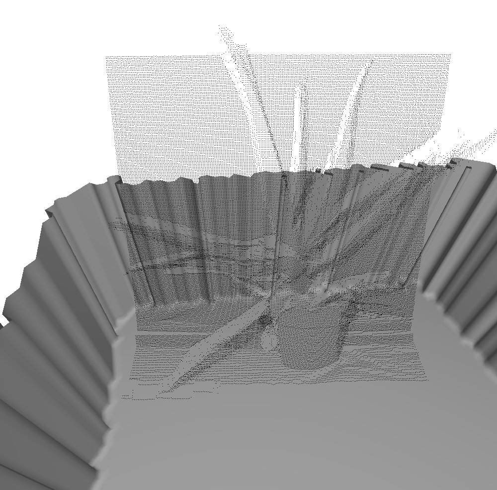
I didn't really line it up here, but ideally we'd have cool features like stairs that we took stereo pictures of. The stairs would be turned into a disparity map, which would be turned into a point cloud, which could be placed in the scene in the correct spot. Then, we add the stairs into the model. That's the plan!
More to come later!
No comments:
Post a Comment